Spiral Wound Gasket
What is Spiral Wound Gasket?
The spiral wound gasket was developed in the early 20th century to meet the increasingly demanding conditions encountered in oil refinery operations. This type of gasket is commonly used with flange surface finishes created using a flange facing machine, which is why we decided to put together this simple overview as an introductory guide for the on-site machinist.
Gaskets used in the oil, gas, and petrochemical industries need to be engineered to cope with high pressures, extreme temperatures, and chemical attack. Fluctuations in the above, along with temperature differential across the flange face and bolt stress relaxation, demand a gasket with flexibility and recovery. The need for the gasket to recover from changing conditions cannot be overemphasized.
Gasket Construction
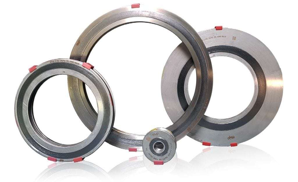
The spiral wound gasket is semi-metallic, comprising of a spirally wound v-shaped stainless-steel strip and a non-metallic filler material, such as graphite or PTFE. Also on the gasket, is a solid outer ring used for centering and controlling compression. This minimizes the risk of material creep through over-tightening.
For the toughest conditions, spiral wound gaskets are available with an additional inner ring. This protects the windings (particularly the filler), from contamination, or attack by the product travelling past the pipeline joint.
Types of Gaskets: Materials
These can be made from CNAF (Compresses non-asbestos fibre), PTFE, Rubber, Teflon or Graphite. Non-metallic gaskets can compress easily with low tension bolting. They’re generally used for low pressure applications and low temperatures. One exception is graphite gaskets, which can be used for temperatures as high as 460 degrees centigrade.
Rubber and elastomer gaskets are not used for pipelines used to transport hydrocarbons.
Metal is used for ring type joints in high-pressure applications, such as oil and gas supply production. RTJs are also used on valves and pipework, assemblies in refineries and other process industries. They seal by an initial line contact or a wedging action as the compressive forces are applied. Metal ring type gaskets are available with oval and octagonal cross sections. Octagonal include the BX type designed to seal pressure up to 20,000 psi, in accordance with API 6A pressure ratings.
Composite Gaskets
Composite gaskets are a combination of metal and non-metal material based on service requirement. Spiral wound, Metal Jacketed, and Kamprofile gasket are well known in composite gasket category. They’re used in a wide range of pressure and temperature services.
Composite gaskets are cost-effective as compared to metal gaskets, but careful handling is required. Composite gaskets are used on raised face, male-female, and tongue-and-groove flanges.
Installation of Spiral Wound Gaskets
- When installing gaskets onto a new flange, or if replacing an old one, the flange faces should be clean and free from indentations and scoring. Cross-face scoring is a major concern as this can lead to joint leakage.
- When scoring is present, the flange surface can be re-machined using a portable machine tool such as a Mirage Flange Facing Machine.
- Gasket manufacturer ‘Flexitallic’ recommend a surface finish of between 3.2 µ to 6.3µ. A surface comparator is a useful tool used to check the finish.
- The flange faces should be parallel and be concentric, without the need for pulling them into position with excessive bolt loads.
- A spiral wound gasket should never be re-used. Always use a new one.
- Before installation, check the gasket is not damaged and that it meets the required correct specification.
- Jointing compounds or lubricants should not be used.
- After installation, check the flange faces are parallel. This can be carried out with a flange gap measurement tool.
Disclaimer: The list below is just a basic overview and should not be taken as formal advice or instructions. Please consult with your gasket manufacturer.
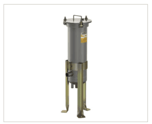

 EH Non-code multi cartridge filter vessel provide economical filtration of a wide variety of liquids in a lightweight, externally polished stainless-steel design, with features including a swing bolt secured, quick opening cover and an internal positive pressure cartridge alignment and sealing plate.
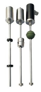
 With magnetically actuated float sensors, switching occurs when a permanent magnet sealed inside a float rises or falls to the actuation level. With a mechanically actuated float, switching occurs as a result of the movement of a float against a miniature (micro) switch. For both magnetic and mechanical float level sensors, chemical compatibility, temperature, specific gravity (density), buoyancy, and viscosity affect the selection of the stem and the float. For example, larger floats may be used with liquids with specific gravities as low as 0.5 while still maintaining buoyancy. The choice of float material is also influenced by temperature-induced changes in specific gravity and viscosity – changes that directly affect buoyancy.
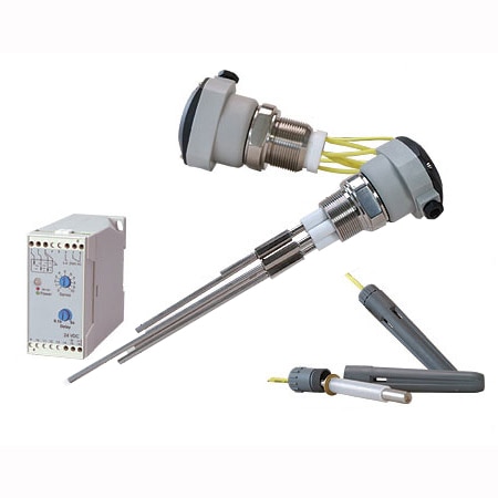 Conductive level sensors are ideal for the point level detection of a wide range of conductive liquids such as water, and is especially well suited for highly corrosive liquids such as caustic soda, hydrochloric acid, nitric acid, ferric chloride, and similar liquids. For those conductive liquids that are corrosive, the sensor’s electrodes need to be constructed from titanium, Hastelloy B or C, or 316 stainless steel and insulated with spacers, separators or holders of ceramic, polyethylene and Teflon-based materials. Depending on their design, multiple electrodes of differing lengths can be used with one holder. Since corrosive liquids become more aggressive as temperature and pressure increase, these extreme conditions need to be considered when specifying these sensors.
 Conductive level sensors use a low-voltage, current-limited power source applied across separate electrodes. The power supply is matched to the conductivity of the liquid, with higher voltage versions designed to operate in less conductive (higher resistance) mediums. The power source frequently incorporates some aspect of control, such as high-low or alternating pump control. A conductive liquid contacting both the longest probe (common) and a shorter probe (return) completes a conductive circuit. Conductive sensors are extremely safe because they use low voltages and currents. Since the current and voltage used is inherently small, for personal safety reasons, the technique is also capable of being made “Intrinsically Safe” to meet international standards for hazardous locations. Conductive probes have the additional benefit of being solid-state devices and are very simple to install and use. In some liquids and applications, maintenance can be an issue. The probe must continue to be conductive. If buildup insulates the probe from the medium, it will stop working properly. A simple inspection of the probe will require an ohmmeter connected across the suspect probe and the ground reference.


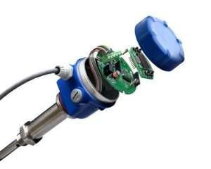
 Flow measurement methods other than positive-displacement flowmeters rely on forces produced by the flowing stream as it overcomes a known constriction, to indirectly calculate
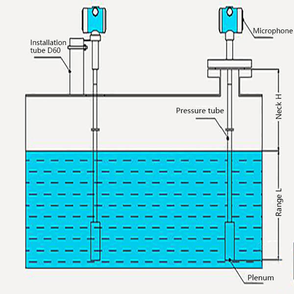
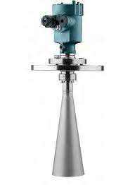
 is a type of flow meter that measures the velocity of a fluid with ultrasound to calculate volume flow. Using ultrasonic transducers, the flow meter can measure the average velocity along the path of an emitted beam of ultrasound, by averaging the difference in measured transit time between the pulses of ultrasound propagating into and against the direction of the flow or by measuring the frequency shift from the Doppler effect. Ultrasonic flow meters are affected by the acoustic properties of the fluid and can be impacted by temperature, density, viscosity and suspended particulates depending on the exact flow meter. They vary greatly in purchase price but are often inexpensive to use and maintain because they do not use moving parts, unlike mechanical flow meters.